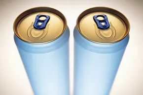
You don’t need a machine shop. You need three empty soda cans and a bit of patience. That’s it.
This project recreates one of the first commercially viable internal combustion alternatives: the Stirling engine. It’s not just a science fair trick. It’s a kinetic sculpture that chuffs and chunks on your desk. It spins a flywheel. It might even generate a few watts of electricity if you’re lucky.
But mostly, it proves a point. Robert Stirling designed this in 1816. He wanted to replace steam with air. Steam was dangerous. It exploded. Boilers blew up with regularity. Stirling’s hot air engine was safer. It used an “economizer,” now called a regenerator, to trap heat and boost fuel efficiency. His brother James helped refine the design. By the mid-19th century, these engines were running foundries.
They weren’t powerful enough to replace steam for heavy industry, though. The industrial revolution demanded raw torque. Steam delivered. Stirling’s engine delivered elegance. Today, it delivers nostalgia.
Why Build a Coke Can Stirling Engine?
Building a Coke can Stirling engine teaches you thermodynamics in a way textbooks can’t. You watch the working fluid expand. You see it contract. You feel the mechanical work being done.
The principle is simple. A heat source, usually a tea light candle, heats the air inside the can. The air expands. It pushes a piston. The air moves to a cooler section. It contracts. The piston moves back. Attach a crankshaft. Add a flywheel. You have an engine.
Most of what you build will be “junk” to the average person. Plastic bottle caps. Old CDs. Balloon rubber. But together, they create motion. It’s home-brew engineering. It’s creative. And it works.
Parts List for DIY Stirling Engine
You need specific materials. Don’t improvise too much. Precision matters here.
- Three (3) aluminum soda cans
- One (1) latex balloon
- Two (2) spoke nipples
- Four (4) 5A electrical terminal blocks
- Steel wool
- One (1) plastic bottle cap
- Steel wire
- Copper wire
- Dowel rod
- Electrical wire
- Fishing line
- Three (3) compact discs (CDs)
- Can opener
- Utility knife
- Super glue
The Mechanics of a Hot Air Engine
How does it actually move?
The air inside becomes the working fluid. When the candle heats the bottom can, the air molecules speed up. They push outward. This pressure drives the piston. The piston is connected to a crankshaft. The crankshaft turns the flywheel. The flywheel carries momentum through the “dead spots” in the rotation.
The air then moves to the upper chamber. The upper chamber is cooler. The air loses heat. It contracts. The vacuum pulls the piston back down. The cycle repeats.
It’s a thermodynamic loop. No combustion inside the cylinder. No sparks. Just heat transfer.
“Stirling’s desire to create a safer alternative to steam was defeated by the need for more power.”
Getting Started: Preparation Steps
Before you cut aluminum, you need to prepare.
Stirling wasn’t the first to try an air engine. But he was the first to make it viable. His 1818 design powered a water pump at a Scottish quarry. That’s the benchmark. You’re aiming for that kind of reliability.
Your first step is gathering the materials. Sort them. Check for damage. Make sure your soda cans are empty and clean. Remove all labels. Glue residue ruins seals.
Next, prepare the balloon. You’ll need to cut a specific shape from it later. Have your utility knife ready. Sharp blades make clean cuts. Blunt blades tear rubber.
Then, look at the CDs. They’ll form the base or the flywheel housing. They need to be clean and free of scratches.
Finally, check your wire. Copper for conductivity. Steel for strength. Fishing line for low-friction links. Each material has a job. Don’t mix them up.
The build begins with the cylinder. The soda can provides the containment. But a can alone doesn’t make an engine. You need pistons. You need seals. You need a way to transfer the linear motion to rotational force.
That’s where the spoke nipples come in. They act as bearings. Smooth rotation is key. Friction kills these engines. If the piston sticks, the cycle stops. You must ensure every moving part spins freely.
Start by marking your cans. Measure twice. Cut once. Aluminum tears easily. Go slow.

The Anatomy of a Can Engine
Larsen’s philosophy is simple enough to be annoying if you don’t follow it. Think like a watchmaker. Precision isn’t just a suggestion here; it’s the difference between a spinning can and a paperweight.
Most builders assume a Stirling engine is complex. It isn’t. The core components are basic. You can build one from oil drums. You can build one from paint cans. Larsen himself pulled one together from assorted pots and pans while stuck in his in-laws’ house for Thanksgiving. It worked.
But for the soda can engine, aluminum is king. It’s cheap. It’s preformed. It’s easy to cut. It won’t survive a race track, obviously. It can’t handle serious load. But it handles the micro-horsepower of a DIY thermodynamic cycle just fine.
Sealing the Deal
The pressure chamber is where the magic happens. Or the misery. It holds the working fluid—usually air—in a closed system. The air heats up. It cools down. It expands. It contracts.
Leaks are the enemy. Everyone wants a perfect seal. Larsen disagrees. You actually need a small, controlled leak. Without it, the chamber becomes a barometer. It just reacts to changes in ambient atmospheric pressure. It does nothing useful. A tiny leak keeps the internal pressure decoupled from the outside world, allowing the cycle to function.
Some enthusiasts swap the air for helium. It reacts better during the thermodynamic cycle. More efficiency. More power. But air is free. Helium is not. Start with air.
The Heartbeat
The drive mechanism translates expansion and contraction into motion. It’s usually attached to the side, but can be integrated into the engine’s structure. It drives a crankshaft.
Larsen calls the crankshaft the most critical part of the entire build. It dictates everything. Timing. Displacer travel. Flywheel speed. Balance. If you mess this up, you mess up the whole engine. Spend time on it. Get it right. It’s not a part to rush.
Momentum and Friction
The flywheel isn’t just a prop. It’s an energy storage device. When the power stroke fires, the flywheel absorbs that energy. When the engine needs to push the displacer back down against friction and resistance, the flywheel gives that energy back.
A balanced flywheel is non-negotiable. If it’s off-balance, the engine has to work harder. You don’t want extra work. You want efficiency. An unbalanced wheel means the displacer hits the top of the chamber and stays there. Dead stop.
The Thermodynamic Dance
The displacer moves the air. It doesn’t create power. It just shifts the air from the hot zone to the cold zone.
Here is the cycle. Heat source at the bottom. Cooling source at the top—ice or cold water usually works. Air heats up. It expands. The displacer moves up. At the top, the air hits the cold surface. It cools. It contracts. The displacer moves down.
Repeat.
This doesn’t happen automatically. You need the drive mechanism, crankshaft, and flywheel to coordinate the movement.
The displacer is typically a rolled piece of steel wool with a light wire through the center. Again, watchmaker logic applies. It needs to slide freely. It needs to fill most of the chamber. It must allow air to flow but restrict it just enough. Minimize friction. Maximize effectiveness. This is the constant theme. Every part fights for efficiency.
The Heat Box
The heat box is a stand. Simple as that. It holds the engine over the heat source.
It feels like a lot of effort for very little output. There is a tangible satisfaction when you finish the build. You troubleshoot the leaks. You balance the wheel. You light the match. You watch it puff along on its own.
Larsen’s fascination started five years ago. It could start for you today.
See It in Action
If you are still skeptical, look at the video. A soda can spinning on nothing but a candle flame. It’s not magic. It’s thermodynamics.
More About Heat Engines
- How Stirling Engines Work
- How Car Engines Work
- How Diesel Engines Work
- How Two-stroke Engines Work
- How a Hot Bulb Engine Works
Sources
- Brown, Buster. “How Hot Air Engines Work.” Hot Air Engines. (Feb. 29, 2012) http://www.hotairengines.com/WorkingDescription/Work.htm
- Editors of Make Magazine; “The Best of Make.” O’Reilly Media, Inc. 2007. Pgs. 306-317.
- Larsen, Jim. StirlingBuilder.com. (Feb. 29, 2012) http://www.stirlingbuilder.com/
- Larsen, Jim. Personal interview. March 2, 2012
- Larsen, Jim. “Eleven Stirling Engine Products You Can Build.” Self-published, January 2012. (Feb. 29, 2012)
- Larsen, Jim. “Quick And Easy Stirling Engine.” Self-published. September 2011. (Feb. 29, 2012)
- Nice, Karim. “How Stirling Engines Work.” HowStuffWorks.com. May 4, 2001. (Feb. 29, 2012) https://www.howstuffworks.com/stirling-engine.htm
- Purvis, Ben. “Dean Kamen developing eco hybrid that will run on anything that burns.” Gizmag.com, June 28, 2009. (March 1, 2012) http://www.gizmag.com/dean-kamen-segway-hybrid-scooter/12096/